Introduction
A single misidentified resistor on a power supply board caused a complete system failure at a manufacturing facility, shutting down production for six hours and costing thousands in lost revenue. The technician had mistaken a 10kΩ resistor for a 1kΩ part—a simple reading error that cascaded into catastrophic consequences. Accurate component identification prevents exactly these costly failures.
Modern circuit boards contain dozens to thousands of components, each marked with specific codes, colors, and symbols. Understanding these marking systems transforms chaotic landscapes of tiny parts into readable maps of electronic functionality.
This guide covers everything you need to identify circuit board components with confidence: fundamental component types, standardized marking systems, proven identification techniques for passive and active components, and practical tips that prevent common mistakes.
TLDR:
- Reference designators (R, C, U) follow IPC-2612 standards to identify component types and PCB locations
- Passive components like resistors use color codes or numerical systems, while capacitors display values directly or use 3-digit codes
- Active components including diodes, transistors, and ICs require careful attention to polarity markings and pinout configurations to avoid installation failures
- Essential identification tools include magnifying glass, multimeter with capacitance/diode modes, and online datasheet resources
- Specialized distributors provide global sourcing for hard-to-find commercial and mil-spec components
What Are Circuit Board Components?
Circuit board components are individual electronic parts mounted on printed circuit boards (PCBs) that each perform specific electrical functions within a circuit. These components range from simple resistors that limit current flow to complex integrated circuits containing millions of transistors that process data and execute instructions.
Identifying components starts with recognizing how they attach to the board, as mounting method affects their appearance and markings.
Two Main Mounting Technologies:
Components attach to PCBs using two distinct methods, each with different visual characteristics:
- Through-hole components feature wire leads that insert through drilled holes in the board and solder on the opposite side, creating mechanically strong connections. These larger components are easier to identify visually and typically show full part numbers or color codes
- Surface-mount components solder directly to pads on the board's surface without requiring through-holes, enabling much higher component density. SMD parts are considerably smaller—often requiring magnification to read markings—and use abbreviated codes rather than full part numbers
Beyond physical mounting, components also classify by their electrical function.
Functional Categories:
Components fall into three broad categories based on how they interact with electrical signals:
- Passive components (resistors, capacitors, inductors) don't require power to operate and can only reduce or store energy
- Active components (transistors, diodes, integrated circuits) can amplify signals, switch current, or perform logic functions, typically requiring external power
- Electromechanical components (connectors, switches, relays) provide physical interfaces or mechanical control of electrical connections
These distinctions form the foundation for accurate component identification, as each category follows different marking conventions and identification methods.
Understanding Component Markings and Reference Designators
Reference Designator System
Reference designators are the letter-number combinations printed on the PCB's silkscreen layer (like R1, C5, U3, Q2) that serve as unique identifiers for each component's type and position.
These designators create a direct link between the physical component on the board, its symbol on the schematic diagram, and its entry in the bill of materials (BOM). The system follows standardized conventions defined by IPC-2612, ensuring consistency across manufacturers and making circuit documentation universally readable.
The letter prefix indicates component type, while the number provides a unique identifier within that category.
Standard Reference Designators:
| Designator | Component Type | Example |
|---|---|---|
| R | Resistor | R15, R203 |
| C | Capacitor | C1, C47 |
| L | Inductor | L2, L8 |
| D | Diode | D5, D12 |
| Q | Transistor (BJT/MOSFET) | Q3, Q7 |
| U | Integrated Circuit | U1, U10 |
| J or P | Connector/Jack/Plug | J4, P2 |
| Y | Crystal/Oscillator | Y1, Y2 |
| F | Fuse | F1, F3 |
| TP | Test Point | TP5, TP12 |
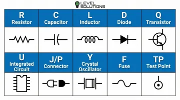
This system lets technicians quickly cross-reference components between the physical board and circuit documentation, making troubleshooting and repair significantly more efficient.
Manufacturer Markings and Codes
While reference designators identify component locations, manufacturers print identification codes directly on component bodies to specify exact part numbers, specifications, and production information. These markings provide your primary source for determining precise component characteristics.
Marking complexity varies by component size:
- Larger components (through-hole resistors, electrolytic capacitors, DIP ICs) display full part numbers, manufacturer logos, and specification codes
- Miniature SMD components use heavily abbreviated alphanumeric codes due to space constraints, requiring lookup tables or databases to decode
- Ultra-small packages (0201, 0402) may have no markings at all, making them identifiable only through circuit position or electrical testing
Production codes provide additional traceability:
- Date codes indicate manufacturing date (often in YYWW format: year and week number)
- Lot codes identify production batches for quality control and traceability
- Country codes show manufacturing location (important for sourcing and compliance)
According to J-STD-609C.01 standards, components must also include material category designations indicating lead (Pb) content—critical information for repair work, as mixing lead-free and leaded solders can compromise joint reliability.
Package Type Indicators
Package designations describe a component's physical form factor and pin configuration using standardized codes. These identifiers help you understand how the component mounts to the board and guide you to the correct datasheet for pinout information.
Common package codes include:
- TO-220: Three-terminal power transistor or voltage regulator with metal mounting tab
- SOT-23: Small outline transistor package with three pins (common for small signal transistors)
- DIP-8, DIP-14, DIP-16: Dual in-line packages with 8, 14, or 16 pins (through-hole ICs)
- SOIC-8, SOIC-16: Small outline IC packages (surface mount versions of DIP)
- QFP-64, QFP-100: Quad flat packages with pins on all four sides (microcontrollers, processors)
Package codes are essential when sourcing replacement components, as electrical equivalents in different packages won't fit the existing PCB footprint.
Industry Standards
Component marking standards from organizations like JEDEC, IPC, and EIA ensure consistency across manufacturers and decades of production. These standards enable accurate identification even when dealing with unfamiliar brands, foreign manufacturers, or components produced 20-30 years ago.
Understanding that these standards exist—and knowing where to find them—gives you confidence that the marking systems you learn apply universally, not just to specific manufacturers or product lines. When you encounter an unfamiliar component, you can rely on these standardized conventions to guide your identification process.
Identifying Passive Components
Resistors: Visual Characteristics
Through-hole resistors are immediately recognizable by their cylindrical body with wire leads extending from each end (axial configuration). The body color—typically tan, blue, or green—provides the background for colored bands that encode the resistance value.
Physical size indicates power rating: small 1/8W resistors measure about 3mm long, while 5W resistors can exceed 20mm in length with substantial lead wire diameter.
Surface-mount resistors appear as small rectangular chips, usually black or dark brown, with numerical codes printed on the top surface. Standard SMD sizes include:
- 0402 (1.0mm × 0.5mm) - often too small for markings
- 0603 (1.55mm × 0.85mm) - minimal markings
- 0805 (2.0mm × 1.2mm) - clear 3-digit codes
- 1206 (3.2mm × 1.6mm) - larger codes, easier to read
The compact size of SMD resistors makes magnification essential for accurate identification.
Resistor Value Identification
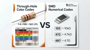
Through-Hole Color Code System:
The color band system, governed by IEC 60062, uses 4-5 colored bands to encode resistance value and tolerance:
- Band 1 (closest to one end): First digit
- Band 2: Second digit
- Band 3: Multiplier (number of zeros)
- Band 4 (often gold or silver): Tolerance
- Band 5 (if present): Temperature coefficient
Example: Brown-Black-Red-Gold = 1-0-×100-±5% = 1,000Ω or 1kΩ with 5% tolerance
SMD Resistor Numerical Codes:
Surface mount resistors use compact numerical systems:
3-digit system: First two digits are the value, third digit is the multiplier (number of zeros to add)
- 103 = 10 × 10³ = 10,000Ω (10kΩ)
- 472 = 47 × 10² = 4,700Ω (4.7kΩ)
4-digit system (precision resistors): First three digits are value, fourth is multiplier
- 1002 = 100 × 10² = 10,000Ω (10kΩ)
Decimal notation: "R" indicates decimal point position
- 4R7 = 4.7Ω
- 0R5 = 0.5Ω
Zero-ohm resistors (jumpers) show either a single black band or 000 marking. These provide a solderable connection between two points.
Capacitors: Types and Appearance
While resistors encode values through colors or numbers, capacitors vary widely in physical form based on their electrical properties.
Electrolytic Capacitors:
These polarized components feature cylindrical aluminum or tantalum bodies with clear polarity markings. A stripe along the body indicates the negative terminal on aluminum electrolytics, while tantalum capacitors may mark the positive terminal instead.
Electrolytic capacitors typically range from 4mm to 18mm in diameter. Power supply filtering applications use them for high capacitance values (1µF to several thousand µF).
According to Panasonic specifications, capacitors 10mm diameter or larger include pressure relief vents—visible as scored patterns on the top surface—to prevent explosion during failure.
Ceramic Capacitors:
Non-polarized ceramic capacitors appear as small disc-shaped components (through-hole) or tiny rectangular chips (SMD). Their small size reflects their typical capacitance range (1pF to 10µF) and suitability for high-frequency applications. Ceramic capacitors lack polarity markings and can be installed in either orientation.
Film Capacitors:
These rectangular components with two radial leads are commonly used in audio circuits and power applications. Film capacitors typically display capacitance and voltage ratings printed directly on the body (e.g., "0.47µF 250V").
Capacitor Value Markings
Direct Marking:
Larger capacitors display values directly: "100µF 25V" indicates 100 microfarads with a 25-volt maximum rating. Always respect voltage ratings—exceeding them risks immediate failure.
3-Digit Code System:
Smaller ceramic capacitors use a numerical code similar to resistors, but with values expressed in picofarads (pF):
- 104 = 10 × 10⁴ = 100,000pF = 0.1µF
- 223 = 22 × 10³ = 22,000pF = 0.022µF
- 475 = 47 × 10⁵ = 4,700,000pF = 4.7µF
Polarity Critical:
Electrolytic and tantalum capacitors must be installed with correct polarity. Reversed polarity causes immediate failure, often with venting or explosion. The negative stripe on aluminum electrolytics and polarity bar on tantalum capacitors provide clear visual indicators that must be verified before installation.

Inductors and Transformers
Inductors appear as coil-shaped components, either with visible wire windings or enclosed in molded bodies. Through-hole inductors may use color codes similar to resistors, while SMD inductors display numerical value codes.
Shielded inductors feature metal enclosures that prevent electromagnetic interference, making them visually distinct from unshielded types.
Transformers are larger multi-winding components with multiple connection pins. They often include pin diagrams or wiring schematics printed on the body or adjacent PCB silkscreen, showing primary and secondary winding connections. Transformers used for power conversion are typically the largest components on a board, while signal transformers may be quite compact.
Identifying Active Components
Diodes: Types and Polarity
Standard diodes have cylindrical bodies with a colored band or stripe marking the cathode end (negative terminal when forward-biased). Through-hole diodes have axial leads extending from each end, while SMD diodes use rectangular bodies with a cathode band consisting of one or more lines on the package end.
Light-emitting diodes (LEDs) have distinctive characteristics:
- Colored or clear lens (shows emission color)
- Longer lead shows anode (positive terminal)
- Flat edge on lens or shorter lead shows cathode
- May include internal reflector visible through clear lens
Specialized diodes serve specific functions:
- Zener diodes provide voltage regulation but look identical to standard diodes
- Schottky diodes offer fast switching and low forward voltage, sometimes using different band colors
- You cannot determine function by appearance alone—part number lookup is essential
Diode Marking Systems
Diodes show part numbers that reveal their specifications. The JEDEC 1N series naming convention is standard for through-hole diodes:
- 1N4148: Small signal diode (200mA, 100V)
- 1N4007: Rectifier diode (1A, 1000V)
- 1N5819: Schottky diode (1A, 40V)
SMD diodes use abbreviated codes printed on the body, requiring manufacturer lookup tables for decoding. The cathode marking (line, dot, or band) provides orientation information regardless of the specific part number.
Testing with Multimeter:
When markings are unclear or worn, use your multimeter's diode test mode to verify polarity and functionality. A functioning diode shows:
- 0.5-0.7V forward voltage drop (silicon diodes)
- 0.2-0.4V forward voltage drop (Schottky diodes)
- OL (open/infinite) reverse voltage
Transistors: BJT and MOSFET
Bipolar Junction Transistors (BJTs) appear as three-terminal devices in various packages:
- TO-92: Small black plastic package with three leads (common for small signal transistors)
- TO-220: Larger package with metal mounting tab (power transistors)
- SOT-23: Surface mount package with three pins
MOSFETs use similar packages but serve different functions (voltage-controlled vs. current-controlled operation). Visual appearance alone cannot distinguish BJTs from MOSFETs—part number identification is essential.
Transistor types require part number verification:
- NPN vs. PNP (BJT): Check part number prefix or datasheet
- N-channel vs. P-channel (MOSFET): Confirm through part number lookup
Transistor Pinout Identification
Pin configuration varies significantly by package type and manufacturer. Never assume pinout—always verify through datasheets before replacing transistors or analyzing circuits.
Common conventions (not universal):
- TO-92 packages often follow Emitter-Base-Collector or Emitter-Collector-Base patterns when viewed from the flat side
- TO-220 packages usually connect the metal tab to the collector (BJT) or drain (MOSFET), with gate/base and source/emitter on outer pins
Incorrect pinout identification during component replacement can destroy the new component instantly when power is applied, and may damage surrounding circuitry.
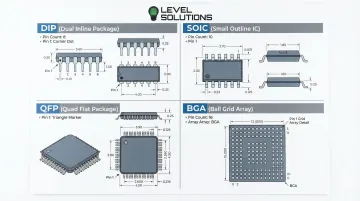
Integrated Circuits (ICs)
ICs come in diverse packages designed for different applications:
- DIP (Dual In-line Package): Two parallel rows of through-hole pins, numbered sequentially
- SOIC (Small Outline IC): Surface mount version of DIP with closer pin spacing
- QFP (Quad Flat Package): Pins on all four sides, used for high pin-count devices
- BGA (Ball Grid Array): Connections underneath package (not visible), requiring X-ray inspection
IC top surfaces show multiple identification elements:
- Part number (primary identifier)
- Manufacturer logo
- Date code (manufacturing date)
- Country of origin
- Pin 1 indicator (dot, notch, or chamfer)
Certain prefixes reveal IC function categories:
- 74xx series: Digital logic (74LS08, 74HC595)
- 555: Timer IC (NE555, LM555)
- LM series: Linear/analog circuits (LM358, LM7805)
- ATmega/PIC: Microcontrollers (ATmega328, PIC16F877)
Temperature range prefixes matter significantly: 54 marks military temperature range (-55°C to +125°C), while 74 marks commercial range (0°C to +70°C). Using commercial-grade parts in military applications risks premature failure.
Advanced and Specialized Components
Voltage Regulators
Three-terminal regulators appear in TO-220 or surface-mount packages with part numbers indicating output characteristics. These devices convert higher or variable input voltages to stable output levels for powering digital circuits, sensors, and other components.
Common regulator identifications:
- 7805: +5V fixed output
- 7812: +12V fixed output
- LM317: Adjustable positive output
- 7905: -5V fixed output (negative regulator)
Input, ground, and output pins follow standard configurations, but always verify pinout before installation. The package marking typically includes the part number and manufacturer code.
Crystals and Oscillators
These timing components feature metallic rectangular or cylindrical bodies with frequency markings stamped or printed on the top surface. Crystals act as the heartbeat of digital circuits, providing the clock signal that synchronizes microcontroller operations.
Common frequency markings:
- 16.000 MHz or 16.000: 16 megahertz crystal (microcontroller timing)
- 32.768 kHz: Real-time clock crystal (watch crystal for timekeeping circuits)
The marked frequency must match circuit requirements exactly. Crystals provide stable frequency references critical for microcontroller operation, communication timing, and precision measurement. Installing the wrong frequency can prevent the circuit from functioning or cause communication errors.
Connectors
Multi-pin connectors provide mechanical and electrical interfaces between circuit boards, cables, and external devices. They come in countless form factors depending on the application and pin count required.
Common connector types:
- Pin headers: Simple rows of pins for board-to-board or board-to-wire connections
- Sockets: Female connectors accepting plugs or other boards
- Terminal blocks: Screw-terminal connectors for field wiring
Pin counts typically appear on the connector body or adjacent silkscreen. For example, "J1 2×5" indicates a 10-pin header in 2-row configuration. The designator "J" prefix identifies connector locations on schematics and PCB layouts.
Tools and Techniques for Component Identification
Visual Inspection Tools
Start with these optical tools for examining component markings:
- Magnifying glass or jeweler's loupe (10x-20x magnification) for reading SMD codes on 0805 packages and smaller
- Smartphone camera with macro mode to capture high-resolution images for analysis
- LED desk lamp with adjustable arm for shadow-free illumination
Multimeter Testing
Digital multimeters verify component values and functionality. Always disconnect components from the circuit or power off and discharge capacitors before testing.
Common test modes include:
- Resistance mode for measuring resistor values
- Capacitance mode for direct measurement (1nF to 100mF range on models like Fluke 287/289)
- Diode test mode to verify polarity and forward voltage drop
In-circuit measurements often produce unreliable results. Parallel paths through other components interfere with readings, making isolated testing the preferred approach.
Component Databases and Online Resources
When physical inspection and testing aren't enough, these digital resources help identify components:
- Manufacturer websites provide official datasheets with specifications and pinout diagrams
- Component databases like Octopart and Findchips cross-reference part numbers across suppliers
- SMD code lookup tools decode abbreviated surface-mount markings to full part numbers
- Electronics forums offer community expertise for obscure or vintage components
For procurement professionals managing large component inventories, accurate identification streamlines sourcing. Distributors specializing in electronic components maintain extensive databases that cross-reference manufacturer codes with current availability.
Practical Tips and Common Identification Mistakes
Common Mistakes to Avoid:
- Confusing resistors with diodes: Both can have cylindrical bodies with colored bands, but diodes have only one band (cathode marker)
- Misreading color codes in poor lighting: Brown and red, or orange and red, appear similar under certain lighting—use bright, neutral-white illumination
- Assuming all three-terminal components are transistors: Voltage regulators, some MOSFETs, and specialized ICs also use three-terminal packages
- Ignoring polarity markings: Reversed electrolytic capacitors or diodes cause immediate failure or component explosion
Best Practices:
- Verify component orientation before soldering: Check polarity markings, pin 1 indicators, and reference designator alignment
- Cross-reference multiple identification methods: Combine visual inspection, part number lookup, and electrical testing for confirmation
- Document component positions before removal: Photograph boards before desoldering components, noting orientation and position
- Use proper magnification: Don't guess at SMD codes—magnify until you can read markings accurately
Sourcing Replacement Components
When replacing identified components, match specifications exactly:
- Voltage ratings: Must meet or exceed original (using lower voltage rating risks breakdown)
- Current capacity: Especially critical for diodes, transistors, and voltage regulators
- Package type: Replacement must fit existing PCB footprint
- Temperature ratings: Match operating temperature range to application requirements
For hard-to-find or obsolete components, specialized distributors like LEVEL SOLUTIONS maintain millions of parts in local ESD-compliant warehouses with access to billions more globally. This includes both commercial and military specifications across all major manufacturers, helping engineers locate exact replacements for discontinued parts.
Frequently Asked Questions
What do the letters on a circuit board mean?
The letters followed by numbers (like R1, C5, D2, U3) are reference designators that identify component type and position on the board. This IPC-2612 standard uses R=resistor, C=capacitor, D=diode, Q=transistor, U=IC, L=inductor, J=connector, and Y=crystal, linking physical components to schematic symbols and bill of materials entries.
How do I identify SMD components without visible markings?
Check PCB silkscreen labels near the component position, examine surrounding components to understand circuit function, and use multimeter testing (resistance, capacitance, or diode modes) to determine electrical characteristics. Ultra-small packages like 0201 and 0402 are typically unmarked, requiring position tracking and electrical testing for identification.
What tools do I need to identify circuit board components?
Essential tools include a magnifying glass or microscope (10x-20x magnification), digital multimeter with capacitance and diode testing modes, LED desk lamp for proper illumination, smartphone camera for documentation, and internet access for datasheet searches and SMD code lookups.
What's the difference between through-hole and surface mount components?
Through-hole components have wire leads that insert through drilled PCB holes and solder on the opposite side. Surface mount components solder directly to pads without requiring holes, enabling over 100 components per square inch compared to approximately 20 for through-hole, which is why SMT now accounts for over 90% of modern assemblies.
How do I identify polarized components to avoid incorrect installation?
Look for these indicators: electrolytic capacitors show a negative stripe, diodes have a cathode band, LEDs have a longer anode lead or flat cathode edge, tantalum capacitors mark the positive terminal, and ICs use pin 1 markers (dot, notch, or chamfer). Always verify polarity before soldering—reversed components fail immediately and may damage surrounding circuits.
How can I find datasheets for components with partial or unclear markings?
Search using the visible portion of the part number plus manufacturer name, use image recognition or reverse image search tools, post clear photos to electronics forums (EEVblog, r/AskElectronics), or contact component distributors with cross-reference databases. Procurement specialists like LEVEL SOLUTIONS can help identify components from partial markings and source replacements from their extensive manufacturer network.